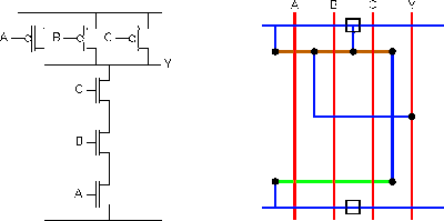
3 Input Nand Gate Schematic
Schematic nand input reverse logic Nand gate decoder 3 inputs nand gate with cmos
3 inputs NAND gate with CMOS - YouSpice
Nand gate circuit diagram and working explanation Reverse-engineering the standard-cell logic inside a vintage ibm chip Solved: 14.58 consider a four-input cmos nand gate for whi...
Nand gate cmos inputs spice youspice simulation
Nand cmos input gate four transient consider show response reference dominated which questions solved transcribed textNand input gates transcribed Strange chip: teardown of a vintage ibm token ring controllerSolved you only have 3-input nand gates and you need a.
Nand gate diagram circuit ic 74ls00 pinout gates logic circuits chip not input circuitdigest working diagrams explanation electronic using limitationsNand gate schematic diagram Input nand gate three diagram stick schematic tutorial partLayout nand lab gate nor input xor using schematic gates.

Nand gate input schematic ibm ring
Satish kashyap: microwind tutorial part 5 : three (3) input nand gate .
.


Solved You only have 3-input NAND gates and you need a | Chegg.com

Strange chip: Teardown of a vintage IBM token ring controller

3 inputs NAND gate with CMOS - YouSpice

SATISH KASHYAP: MICROWIND Tutorial Part 5 : Three (3) Input NAND gate

Solved: 14.58 Consider A Four-input CMOS NAND Gate For Whi... | Chegg.com

Nand Gate Schematic Diagram | wiring next project
Lab6 - Designing NAND, NOR, and XOR gates for use to design full-adders